Masters of Science | Mining Engineering
West Virginia University (USA)
Advisor: Ihsan Berk Tulu
Itasca Mentor: Ehsan Ghazvinian

Introduction
In the United States, underground limestone mines use the room-and-pillar method in flat-lying bedded formations, where two essential factors for safe working conditions are pillar and roof span stability. The roof span between pillars must be stable to provide safe access to the working areas. Additionally, as the mine becomes larger, the primary means of ceiling support are the pillars of rock left in place between the rooms of mined-out rock. Unstable pillars can result in rock sloughing from the pillar as well as the collapse of the roof if one or more pillars should fail.
In the past, pillar and roof span dimensions were mainly based on experience in nearby mines, which were developed by trial and error or designed by rock engineering experts on a case-by-case basis. Consequently, the National Institute for Occupational Safety and Health (NIOSH) has developed guidelines for designing stable pillars and roof spans in stone mines. However, in the guidelines, the only structural geology parameter influencing the strength of a stone mine pillar studied is the existence of large discontinuities crossing the pillar. Hence, the influence of more than one joint set and natural fractures on the localized failures and general stability of a pillar has not been studied. Therefore, the main objective of this study was to develop a pillar strength estimation methodology to explain the short-term strength and failure mechanisms of underground limestone mine pillars by modeling the naturally existing fractures. This included four major tasks:
- Stone mine database analysis.
- Synthetic Rock Mass (SRM) generation.
- Rock block up-scaling.
- Analysis of the failure mechanism of stone mine pillars.
UDEC version 7 was used in two main areas: generation of Discrete Fracture Networks (DFNs) and assessment of the pillar strength in the up-scaling process from laboratory sample size to field pillar size using the Synthetic Rock Mass (SRM) approach.
Task 1: Stone Mine Database Analysis
The input parameters were collected from the U.S. Stone Mine Database and reduced according to their three UCS categories: 1) low strength (LS); 2) medium strength (MS); and 3) high strength (HS). To reduce the input parameters, a series of analysis of variance (ANOVA) tests were performed that established whether the categorized data groups were statistically different from one another. By using the reduced parameters, a set of parametric model runs were performed.
Task 2: Synthetic Rock Mass (SRM) Generation
A novel SRM approach was utilized to represent a stone mine pillar in UDEC. As part of this task, Bonded Particle Models (BPMs) and DFNs were generated.
In order to generate a BPM, a standard size lab specimen (0.05 x 0.10 m) was calibrated with plastic zone elements using the conventional Mohr-Coulomb Failure Criteria. The plastic zone properties were derived from the standard size lab specimen. The specimen was then scaled up (0.20 x 0.40 m) using the Hoek-Brown Scaling equation to form a BPM by Trigon discretization logic. To capture the scaled-up properties, previously established local micro calibration procedures were performed.
In order to generate the DFNs from the field parameters (derived in Task 1), a DFN module embedded in UDEC was utilized. Based on the three categorized data groups, three different DFN models were generated. In the generation of DFNs, based on field surveys two nearly-perpendicular joint sets were introduced as vertical ( dip angle) and horizontal ( dip angle). Lastly, the SRM models were generated by coupling the BPMs and DFNs.
Task 3: Rock Block Up-Scaling
The SRM models generated in Task 2 were then systematically up-scaled from 0.20 x 0.40 m to an average field specimen size with different width-to-height ratios. In order to eliminate the particle-size-related biases in every scale, a homogenization process was utilized in the interim stages of the up-scaling operations by capturing SRM responses with a new, joint-free BPM. By repeating these processes, a general stone mine pillar rock mass was established.
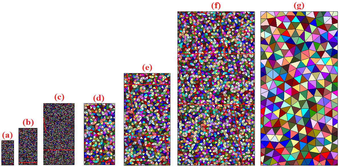
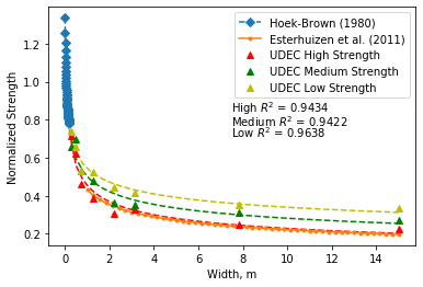
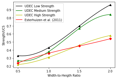
In the homogenization stages, the micro-cohesion and micro-friction properties of the Trigon Contacts were degraded. It was found that the numerically calculated pillar strengths are in good agreement with the empirical formula of pillar strength from the NIOSH guidelines. Figure 1 shows how the established SRM model systematically is up-scaled. Figure 2 shows the numerically estimated pillar strength with the constant width-to-height ratio of 0.5 for LS, MS, and HS while Figure 3 presents the pillar strength estimations for 15.0 m wide pillars with various width-to-height ratios of 0.5, 1.0, 1.5, and 2.0.
Task 4: Progressive Failure Mechanism of Stone Mine Pillars
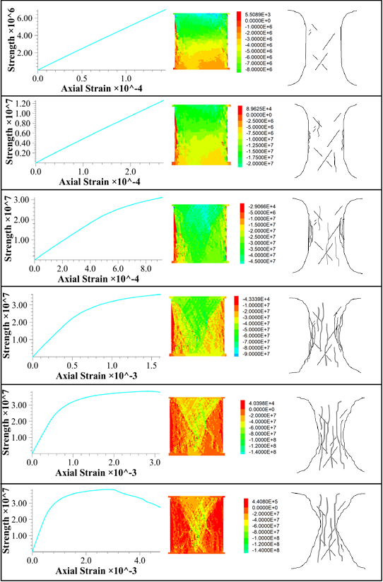
The failure and progressive failure mechanism of the pillars, using the calibrated numerical models, were then studied and a methodology was developed (in order to capture the findings as well as to create a link between intact lab size rock specimens and field size pillars with naturally existing joint sets). Figure 4 visualizes loading stages and failure progression as the loading increases for one pillar model having the width-to-height ratio of 1.0 together with stress contours and sketches of pillars made by Roberts et al. (2007) based on field observations.
Using UDEC for Numerical Simulations of Specimens
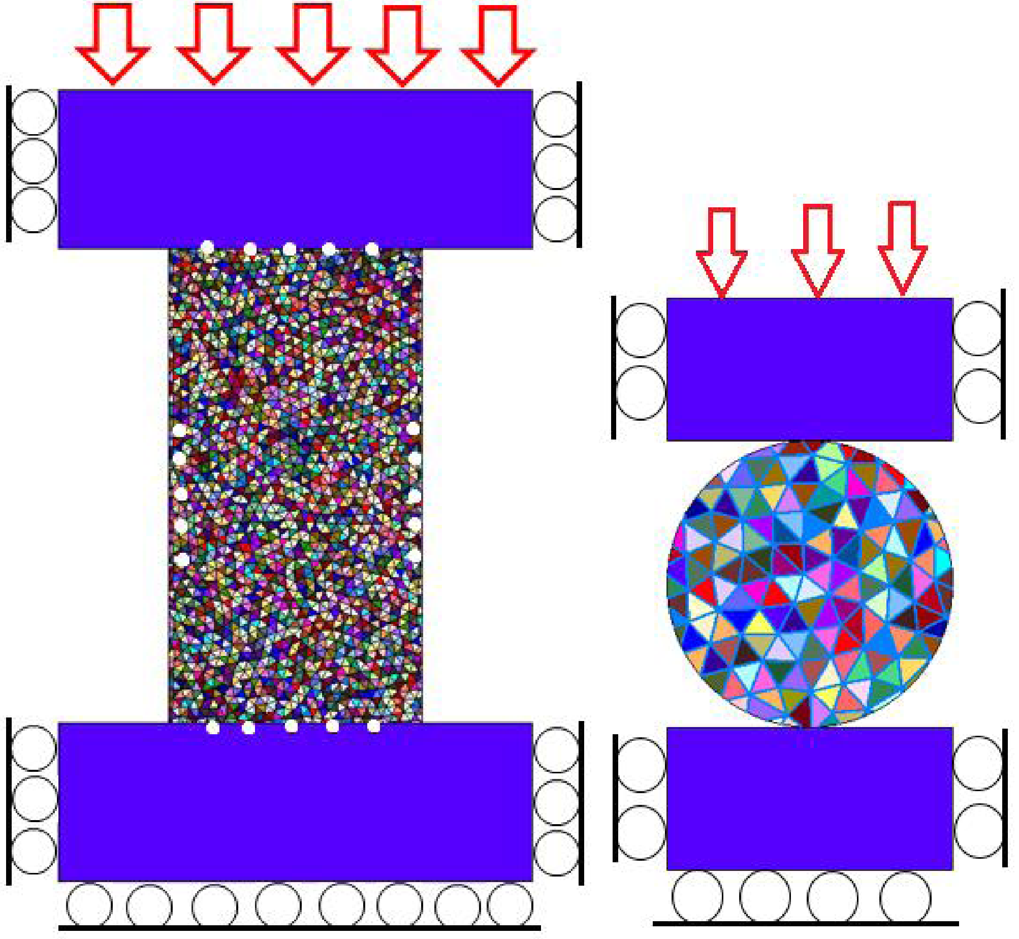
UDEC models were generated as seen in Figure 1. In the upper and lower part of the rock medium, contactless (non-cohesive, non-frictional, non-tensional) steel platens were located and roller boundary conditions were used. The models were then axially loaded in the downward direction (red arrows) by applying a constant velocity on the upper platen. In Figure 5, the white dots in the model indicate the data collection points. Finally, the stresses were collected as forces from both zone elements and bottom boundary reactions with FISH.
Conclusions
In order to investigate the mechanical behavior of underground limestone pillars, a methodology was developed and applied in UDEC. SRM models were generated from test results of laboratory rock specimens as well as field geological structure surveys by introducing BPMs and DFNs. After understanding the effect of micro-parameters on the macro-responses and establishing calibrated bonded particle models, three different DFN models were generated based on the categorized data groups. SRM methodology provides a holistic view of pillar strength estimation from laboratory scale to in-situ. Pillar strengths estimated from the study agreed with the literature. Further studies on failure mechanisms revealed that a realistic simulation of pillars is achieved with the coupling methodology of BPMs and DFNs in the UDEC.
Acknowledgement/Disclaimer
This study was sponsored by the Alpha Foundation for the Improvement of Mine Safety and Health, Inc. The views, opinions, and recommendations expressed herein are solely those of the authors and do not imply any endorsement by the Alpha Foundation, its directors, and staff.
Acknowledgements
The authors would like to sincerely thank Dr. Gabriel S. Esterhuizen to share his valuable knowledge on the stone mines. Finally, the authors would like to sincerely thank Dr. Bo-Hyun Kim for sharing his knowledge on the generation of Discrete Fracture Networks, and numerical simulations in discrete element modeling.
